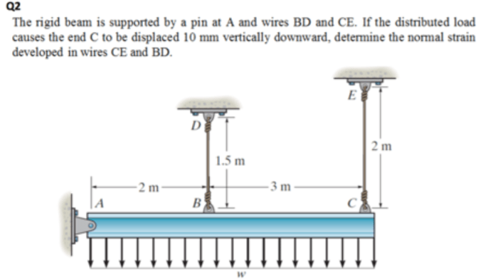
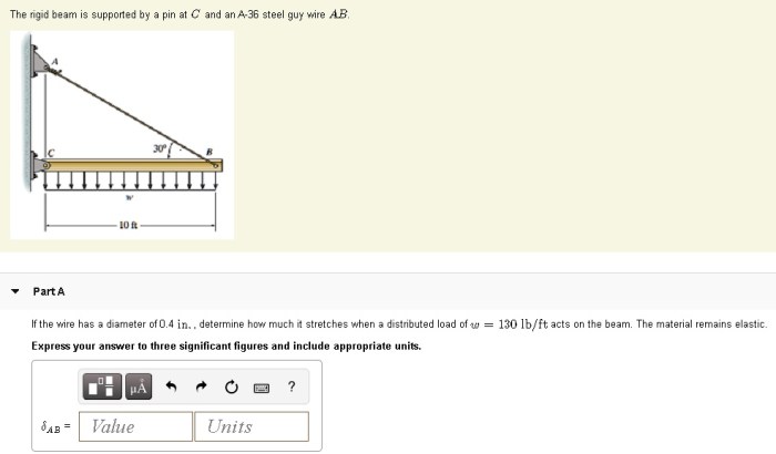
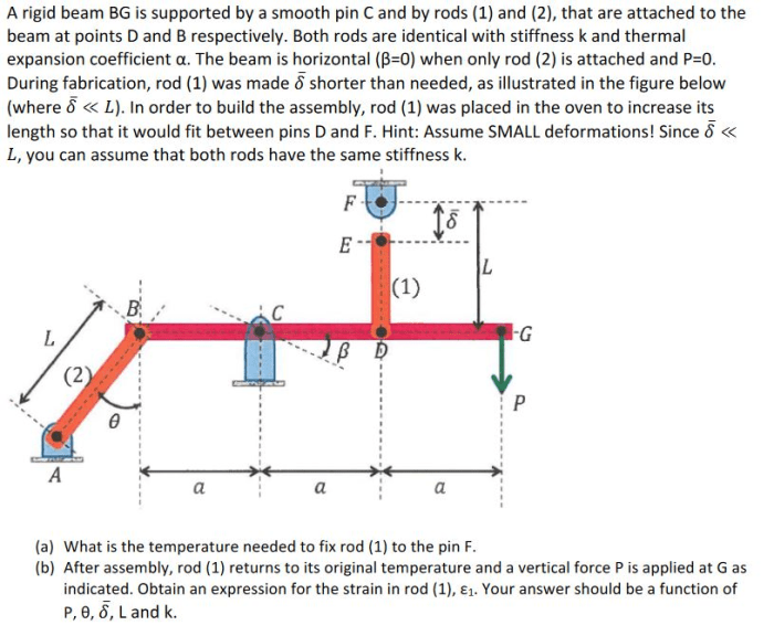
The rigid beam is supported by a pin at c – The rigid beam supported by a pin at C is a fundamental structural element widely employed in various engineering applications. Its unique design and support system give rise to intriguing force distributions and stress patterns, making it a captivating subject for exploration.
This comprehensive analysis delves into the intricacies of this beam, examining its structural components, force analysis, stress and strain distribution, design considerations, and practical applications.
The pin support at point C plays a crucial role in maintaining the beam’s stability and influences the distribution of forces within the structure. Understanding the mechanics of this support is essential for optimizing the beam’s performance and ensuring its longevity.
Structural Elements and Support

The rigid beam under consideration is supported by a pin at point C. This pin support provides a fixed point of rotation, allowing the beam to rotate about the pin while preventing any vertical or horizontal movement. The rigidity of the beam ensures that it can withstand significant loads without significant deformation, making it suitable for various structural applications.
Pin Support
The pin support at C plays a crucial role in maintaining the beam’s stability. It provides a single point of contact between the beam and the supporting structure, allowing the beam to rotate freely about this point. This rotation prevents the development of bending moments at the support, ensuring that the beam is subjected to axial forces only.
Beam Rigidity
The rigidity of the beam is essential in relation to its support at C. A rigid beam is one that resists deformation under load, maintaining its shape and dimensions. This rigidity ensures that the beam can transfer loads efficiently from the point of application to the pin support without significant deflection.
A flexible beam, on the other hand, would experience bending under load, potentially leading to failure.
Force Analysis: The Rigid Beam Is Supported By A Pin At C
Forces Acting on the Beam
The rigid beam supported by a pin at C is subjected to various forces, including:
- External loads applied to the beam
- Reactions at the pin support (vertical and horizontal)
Pin Support Reactions, The rigid beam is supported by a pin at c
The pin support at C provides reactions that counteract the external loads applied to the beam. These reactions consist of:
- Vertical reaction: This reaction prevents the beam from moving vertically and is equal to the sum of the vertical components of the external loads.
- Horizontal reaction: This reaction prevents the beam from moving horizontally and is equal to the sum of the horizontal components of the external loads.
Force Distribution
The pin support at C affects the distribution of forces within the beam. The reactions at the support create axial forces in the beam, which are distributed along the beam’s length. The magnitude and direction of these axial forces vary depending on the location of the external loads.
Stress and Strain

Stress Distribution
The stress distribution within the rigid beam supported by a pin at C is influenced by the pin support. The pin support creates a discontinuity in the stress field, resulting in higher stress concentrations near the support. The maximum stress occurs at the point where the beam is fixed to the pin, and it decreases gradually along the beam’s length.
Strain Distribution
The strain distribution within the beam is directly related to the stress distribution. Higher stresses lead to higher strains. The strain is maximum at the point of maximum stress and decreases along the beam’s length. The strain distribution provides insights into the deformation of the beam under load.
Failure Modes
The stress analysis of the rigid beam supported by a pin at C can help identify potential failure modes. The beam may fail due to:
- Tensile failure: Occurs when the stress exceeds the material’s tensile strength.
- Compressive failure: Occurs when the stress exceeds the material’s compressive strength.
- Shear failure: Occurs when the shear stress exceeds the material’s shear strength.
Design Considerations
Material Selection
The choice of material for the rigid beam supported by a pin at C depends on several factors, including:
- Strength requirements
- Stiffness requirements
- Corrosion resistance
- Availability and cost
Dimensions
The dimensions of the beam are determined based on:
- Load capacity
- Deflection limits
- Material properties
- Support conditions
Support Conditions
The design of the pin support at C is critical for the beam’s performance. Factors to consider include:
- Pin size and material
- Bearing surface area
- Lubrication
Applications and Examples

Applications
Rigid beams supported by pins at C are commonly used in various structural applications, including:
- Bridges
- Buildings
- Crane beams
- Offshore structures
Examples
| Application | Key Design Parameters | Performance Characteristics |
|---|---|---|
| Bridge girder | Load capacity, deflection limits, material strength | High strength-to-weight ratio, long span lengths |
| Building beam | Load capacity, fire resistance, aesthetic considerations | Efficient load transfer, minimal deflection, fire safety |
| Crane beam | Load capacity, fatigue resistance, safety factors | High load-bearing capacity, durability under repeated loading |
Detailed FAQs
What is the primary function of the pin support at C?
The pin support at C provides rotational freedom while preventing lateral movement, allowing the beam to rotate freely about the pin while maintaining its position in the vertical plane.
How does the pin support affect the force distribution within the beam?
The pin support introduces a reaction force at point C, which counteracts the external forces applied to the beam. This reaction force creates a moment that affects the distribution of shear forces and bending moments along the beam’s length.
What are the potential failure modes of a rigid beam supported by a pin at C?
Potential failure modes include bending failure due to excessive bending moments, shear failure due to high shear forces, and buckling failure due to compressive forces exceeding the beam’s critical buckling load.